Objective:
This basic lab demonstrates how to set up a network with 4 PCs, 2 routers, and 2 switches in Cisco Packet Tracer. The configuration will include static routing, IP addressing, and testing connectivity between the devices, with detailed information about which ports each device connects to.
Step 1: Equipment Used
- Routers: 2 routers (Router 1 and Router 2)
- Router 1 (R1): Connected via GigabitEthernet0/1 and GigabitEthernet0/0
- Router 2 (R2): Connected via GigabitEthernet0/1 and GigabitEthernet0/0
- Switches: 2 switches (Switch 1 and Switch 2)
- Switch 1 (S1): Connected to Router 1 on GigabitEthernet0/1, and to PC 1 and PC 2
- Switch 2 (S2): Connected to Router 2 on GigabitEthernet0/1, and to PC 3 and PC 4
- PCs: 4 PCs (PC 1, PC 2, PC 3, and PC 4)
- PC 1: Connected to Switch 1 on FastEthernet0/1
- PC 2: Connected to Switch 1 on FastEthernet0/2
- PC 3: Connected to Switch 2 on FastEthernet0/1
- PC 4: Connected to Switch 2 on FastEthernet0/2
- Cables: Ethernet cables (Copper straight-through for PC-to-switch and router-to-switch connections; router-to-router is typically done using a serial connection, but in this example, copper straight-through cables are used.)
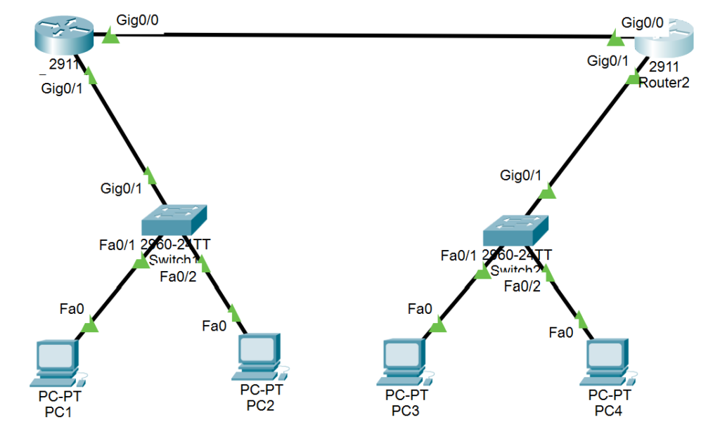
Step 2: Network Topology
Here is the network topology, specifying the exact ports:
- Router 1 (R1):
- GigabitEthernet0/1 connected to Switch 1 (S1)
- Serial0/0/0 connected to Router 2 (R2) on GigabitEthernet0/0
- Router 2 (R2):
- GigabitEthernet0/1 connected to Switch 2 (S2)
- Serial0/0/0 connected to Router 1 (R1) on GigabitEthernet0/0
- Switch 1 (S1):
- GigabitEthernet0/1 connected to Router 1 (R1)
- FastEthernet0/1 connected to PC 1
- FastEthernet0/2 connected to PC 2
- Switch 2 (S2):
- GigabitEthernet0/1 connected to Router 2 (R2)
- FastEthernet0/1 connected to PC 3
- FastEthernet0/2 connected to PC 4
Step 3: Configuring IP Addressing
I assigned IP addresses to all devices in the network:
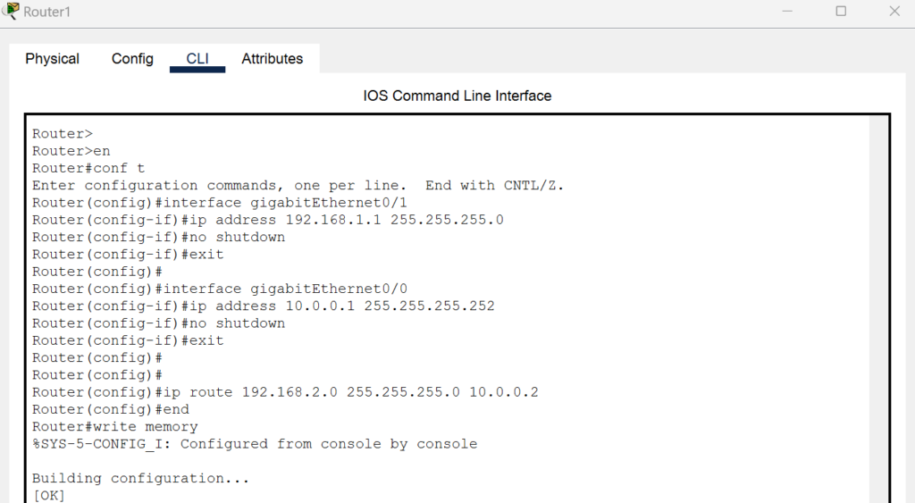
- Router 1 (R1):
- GigabitEthernet0/1: 192.168.1.1/24 (connected to Switch 1)
- GigabitEthernet0/0: 10.0.0.1/30 (connected to Router 2)
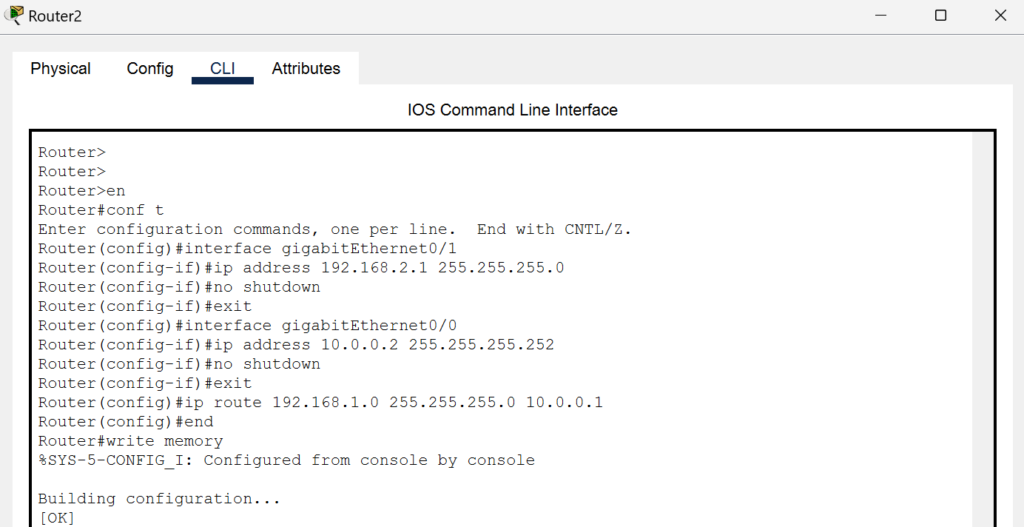
- Router 2 (R2):
- GigabitEthernet0/1: 192.168.2.1/24 (connected to Switch 2)
- GigabitEthernet0/0: 10.0.0.2/30 (connected to Router 1)
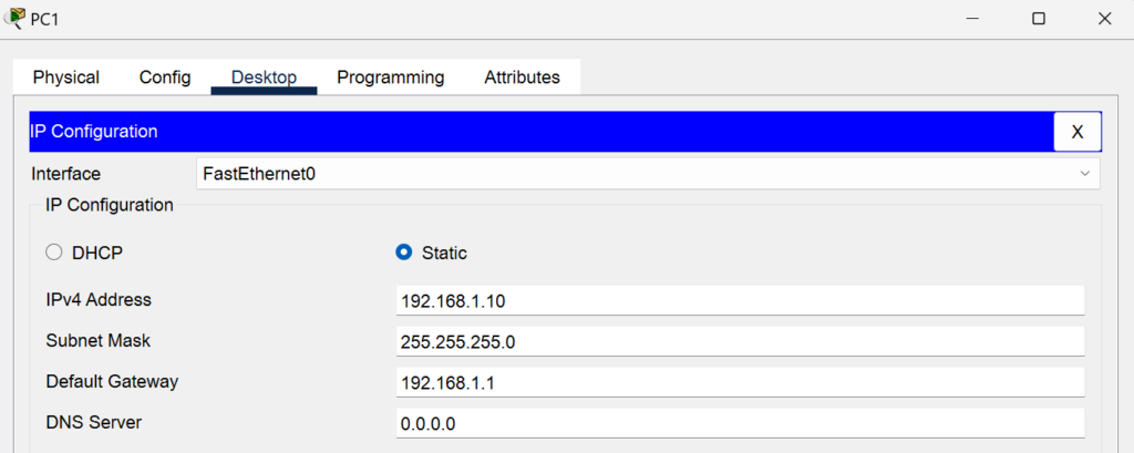
- PC 1:
- IP Address: 192.168.1.10/24
- Gateway: 192.168.1.1
- Port: FastEthernet0/1 (connected to Switch 1)
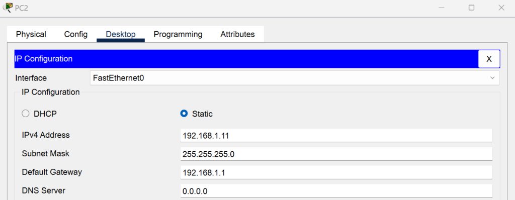
- PC 2:
- IP Address: 192.168.1.11/24
- Gateway: 192.168.1.1
- Port: FastEthernet0/2 (connected to Switch 1)
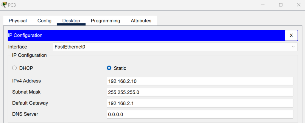
- PC 3:
- IP Address: 192.168.2.10/24
- Gateway: 192.168.2.1
- Port: FastEthernet0/1 (connected to Switch 2)
- PC 4:
- IP Address: 192.168.2.11/24
- Gateway: 192.168.2.1
- Port: FastEthernet0/2 (connected to Switch 2)

Step 4: Configuring Routing
Next, I configured static routes on both routers to enable communication between the networks.
- On Router 1 (R1):
- Add the static route to reach the 192.168.2.0 network via Router 2’s g0/0 interface:
R1(config)# ip route 192.168.2.0 255.255.255.0 10.0.0.2
- On Router 2 (R2):
- Add the static route to reach the 192.168.1.0 network via Router 1’s g0/0 interface:
R2(config)# ip route 192.168.1.0 255.255.255.0 10.0.0.1
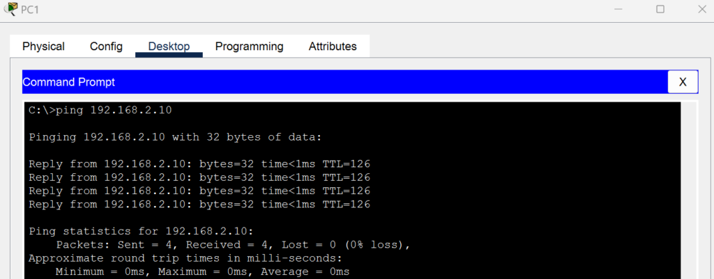
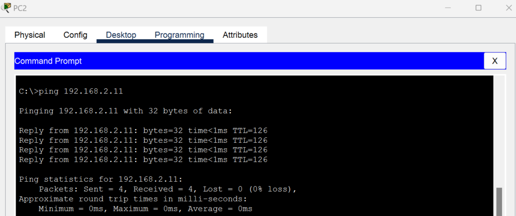
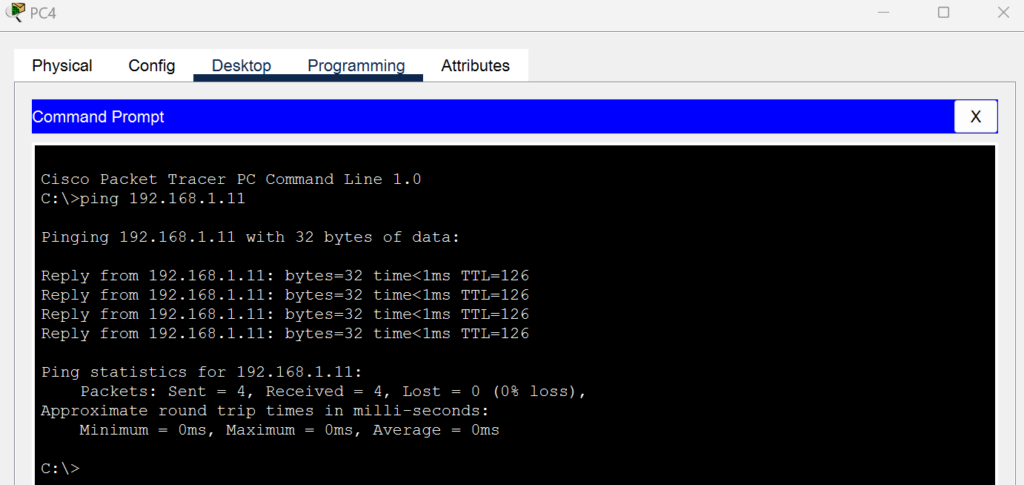
Step 5: Testing Connectivity
I tested the network connectivity using the ping command between PCs across different subnets.
- From PC 1, ping PC 3:
ping 192.168.2.10 - From PC 2, ping PC 4:
ping 192.168.2.11 - From PC 3, ping PC 1:
ping 192.168.1.10 - From PC 4, ping PC 2:
ping 192.168.1.11

Step 6: Troubleshooting
In case the pings fail, I troubleshoot using the following steps:
- Verify IP addresses: Check that the IP addresses are correctly configured on each device.
- Check routing: Ensure the static routes are correctly configured on both routers.
- Check cable connections: Make sure the cables are connected to the correct ports.
- Check interfaces: Use the
show ip interface briefcommand to verify that the interfaces on both routers are up and operational.
Conclusion
This lab in Cisco Packet Tracer helped me simulate a more complex network and practice CCNA concepts like IP addressing, routing, and troubleshooting. It gave me valuable hands-on experience in configuring and verifying connectivity in a small network with 4 PCs, 2 routers, and 2 switches.